1.5/2 V power supply
"knife" switch
3 ![]() ,
5 Watt resistor
,
5 Watt resistor
5 ![]() ,
5 Watt resistor
,
5 Watt resistor
10 ![]() ,
5 Watt resistor
,
5 Watt resistor
25 ![]() ,
5 Watt resistor
,
5 Watt resistor
0-1 A ammeter
0-3 V voltmeter
5 connecting wires
In this lab, you will construct a simple circuit using a single known resistance, R. Then you will use an ammeter to measure the current, I, through the resistance and a voltmeter to measure the potential difference, V, across the resistance. With this data, you can check the validity of Ohm's Law (V = IR) in the circuit.
|
1.5/2 V power supply |
"knife" switch |
3 |
|
5 |
10 |
25 |
|
0-1 A ammeter |
0-3 V voltmeter |
5 connecting wires |
IMPORTANT: In this lab you will use ONLY the "COMMON" and "1.5/2 VDC" terminals on the power supply. Connecting the circuit to any other terminals will certainly result in destruction of equipment and might well be hazardous to you and your lab partner. This will NOT be treated as a "harmless prank". Disciplinary action will be taken, and you will be responsible for damaged equipment.
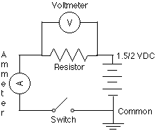 Set
up the circuit depicted in the schematic diagram shown at right
using the 3
Set
up the circuit depicted in the schematic diagram shown at right
using the 3
STOP!! Have your teacher check your circuit before you close the switch!
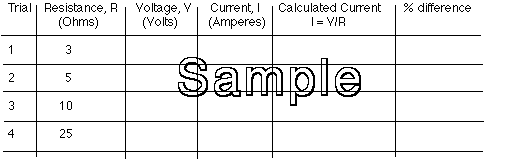
1. For each trial, calculate the expected current based on the resistance and measured voltage using Ohm's Law. Record your results in your data table, and be sure to show a sample calculation.
2. For each trial, calculate the percent of difference between the calculated and measured current in the circuit. Record your results in the data table. Show a sample calculation.
1. When the resistance in the circuit went up, what happened to the current in the circuit?
2. Do you think that your circuit follows Ohm's Law? Why or why not?